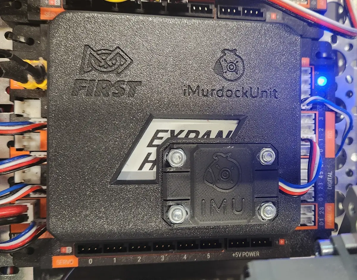
iMurdockUnit - An External IMU Enclosure
Background
The Problem
Over our first three competitions, team 10809 Crow Force sacrificed points during autonomous and tele-op when our robot became disoriented, causing failures in autonomous trajectory sequences and field-centric driver control. These failures seemed to coincide with collisions between exposed metal on our robot and other conductive objects on the field such as the 2023-'24 CENTERSTAGE™ game's truss supports and other robots.
By finding a way to reproduce failures with truss contact and then printing Inertial Measurement Unit (IMU) orientation telemetry to the driver hub, we observed our gyroscope and accelerometer readings drop to all zeros after metal contact that would persist until repowering the robot. After reading FIRST's article “Managing Electrostatic Discharge Effects”, we learned that these IMU flatlines could result from ESD: electrostatic discharge. The FIRST Tech Challenge Blog's 2023-11-21 post “Unexpected IMU Reset” lead us to suspect REV Robotics' 2022-09-23 IMU hardware changes made to REV-31-1595 Control Hubs. We tested this hypothesis by switching our robot's control hub with an older model and observing a reduction in IMU resets. Unfortunately, older generation control hubs are a luxury of established teams and they won't survive the playfield forever.
Note: To determine which type of IMU your control hub contains without knowing its manufacture date, see the control hub's web interface as explained by REV's IMU documentation.
Existing Solutions
If your robot suffers from similar IMU issues or other electrical failures that might be caused by ESD, try these existing solutions first. Combine them to build up “defense in depth”, layering redundant protections that are less likely to all fail at once.
-
Add a REV-31-1269 Resistive Grounding Strap between a spare XT30 connector and the metal chassis of your robot. The bump in the middle of this wire hides a resistor that lets accumulated electric charge safely trickle from the metal frame into your control and expansion hubs, lowering the voltage (difference in density of electric charge) between them.
Keep in mind that most extruded aluminum channel is “anodized”: coated in a non-conductive layer to prevent corrosion. Cut through it with a star washer or by scraping to make good electrical contact between the grounding strap's ring terminal and your robot's frame.
Cover exposed metal along the outside of your robot with an electrically insulating material where it could touch the truss or other robots. Metal-to-metal contact would allow electric charge to rush in or out of your robot's frame to balance with the other object.
Also cover any visible metal on wiring connectors and empty sockets with electrically insulating material like electrical tape. When the voltage between your robot's frame and its wiring grows too high, electricity can jump through the air one centimeter or more as a visible spark; This is the discharge of electricity that ESD refers to.
Update to REV's early-access Control Hub OS version 1.1.4 or newer, which claims to reduce the chance of IMU resets. This FIRST Tech Challenge Blog post from 2024-02-24 explains how to install the early-access version.
Our Solution
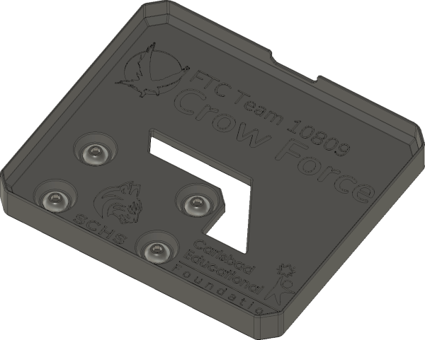
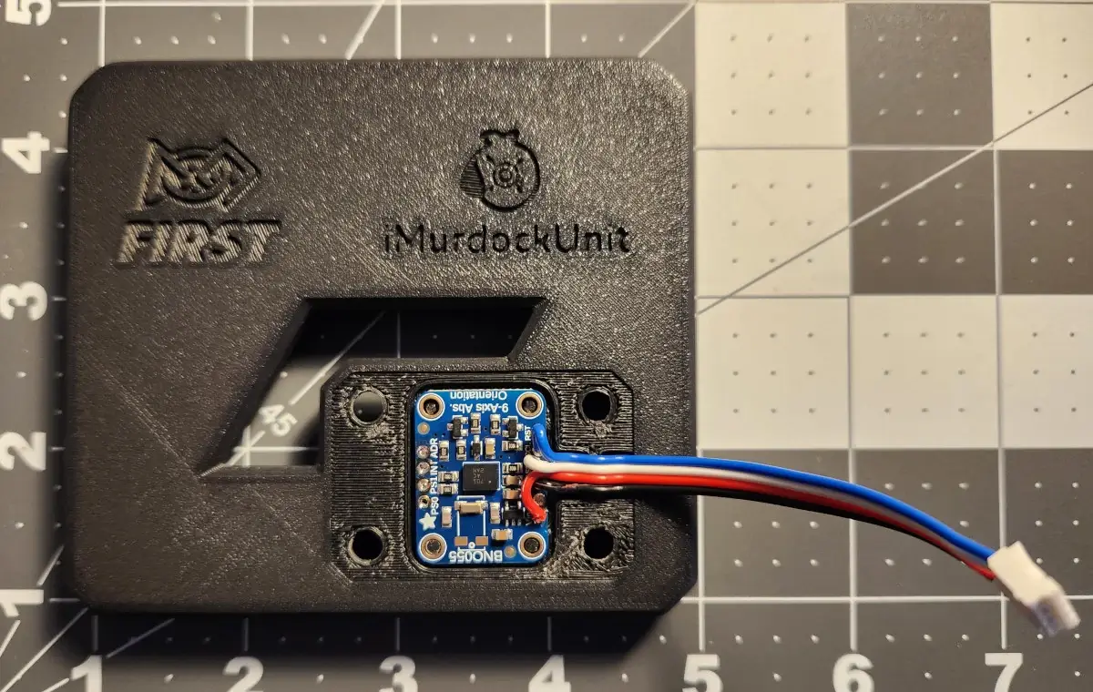
Once your team has applied the previous suggestions for mitigating static, your new control hub's IMU may still reset when shocked. Fortunately, external IMU sensor boards using the same chip as original control hubs can still be purchased! Read on for a simple guide to buying, assembling, attaching, and configuring a replacement IMU in a 3D-printed enclosure designed by team 10809 Crow Force and the mentors of Sage Creek High School.
Design Goals
The external IMU's position and rotation are aligned with a hub's internal IMU except raised towards the iMurdockUnit by 27.2mm. Gyroscope readings will match the internal IMU without code changes, and accelerometer readings will only vary slightly while rotating.
The I2C sensor cable is strain-reliefed to prevent tugging on its soldered connections to the external IMU.
Hardware
Required Tools
To assemble an iMurdockUnit, you will use the following tools:
- 3D Printer
- Soldering Iron
- Wire Cutters
- Wire Strippers
Required Materials
One iMurdockUnit is made from the following components:
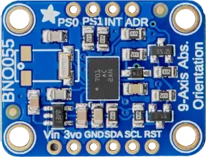
- Adafruit 2472: BNO055 IMU
Breakout Board
This sensor board features the same Bosch BNO055 IMU chip that previous generation control hubs included.
- Semi-Rigid 3D Printer Filament (such as PLA)
The printed part press-fits onto the top of a control or expansion hub, so more flexible plastics will conform and hold on better.
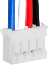
- REV Robotics
REV-31-1407-PK4 or Equivalent, ≥10cm
Only half of this sensor cable requires a JST PH4 connector to fit into the control or expansion hub's I2C ports; The other end will directly solder to the IMU breakout board. To simplify wiring with these instructions, find a cable that matches REV's sensor wire colors: blue (pin 1), white, red, black.
- Lead-Free Solder
- 4× Button-Cap M4 Screws, ≥8mm
- 4× M4 Nyloc Nuts
- Super Glue (Cyanoacrylate)
Assembly Instructions
Warning: Safety first. Wear safety glasses when cutting wire or while soldering, and be careful with the cutting end of wire cutters and wire strippers.
Begin 3D printing the base and cap pieces: STEP file, STL file.
Use wire cutters to cut the sensor cable, leaving about 10cm of cable connected to the JST PH4 connector that plugs into control or expansion hubs. Discard the rest of the cable.
At the cut end of the remaining sensor cable, pull the cable's individual wires apart by about 2cm so that end appears frayed.
Use wire strippers to expose about 4mm of copper from wires at the sensor cable's frayed end.
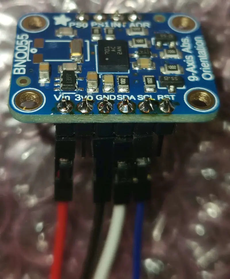
In a well ventilated area, use a soldering iron and lead-free solder to connect the following stripped sensor cable wires to the Adafruit 2472 IMU breakout board:
Note: Don't match the photo; it is only for reference matching wire colors to breakout board pads. In the iMurdockUnit, these wires must come out the top of the breakout board.
- Red:
Vin - Black:
GND - White:
SDA - Blue:
SCL
Use this technique for each wire:
-
Insert the stripped end of the wire through the top of the board (the side labeled “BNO055”) until the wire's insulation almost contacts the board.
Note: Do not tin the wire first, or else you may bend unseen wire strands.
Apply solder where the wire protrudes from the bottom, being careful not to connect with neighboring pads.
Trim excess wire from the solder blob.
- Red:
Wait for both 3D printed parts from step 1 to complete, and remove any scaffolding.
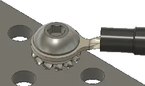
Use super glue to affix four M4 nyloc nuts into the corner slots of the smaller 3D printed cap piece labeled “IMU”. With the lettering facing upwards, the nuts' threaded sides should face downwards. Be careful not to get super glue inside the threads.
-
Set the IMU breakout board onto the four tapered alignment pins within the larger 3D printed base's cutout. Centered within those pins is an engraving of a small rectangle with a dot in one corner; Locate the breakout board's black IMU chip with white dot, and match their orientations. Labels on the breakout board should be upside down compared to those on the 3D printed part.
-
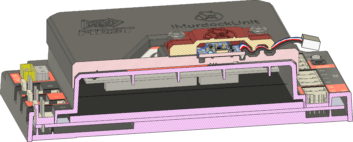
The sensor cable should extend from the IMU breakout board over a channel in the larger 3D printed base. Align the cable with this channel and then press the smaller 3D printed cap on top with text from both 3D printed pieces in the same orientation. Maintain pressure to constrain the sandwiched IMU and cable while threading four button-cap M4 screws from the bottom of the base through the cap; Tighten the screws evenly, and do not over-tighten them. The following cut-away rendering illustrates how the sensor cable should fold between channels in the 3D printed parts to create strain relief.
Installation
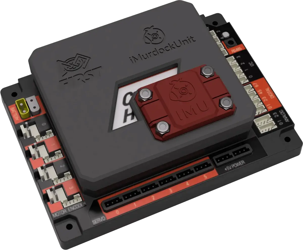
The assembled iMurdockUnit rides on a control or expansion hub's orange hump with diagonal white stripe. Rotate the iMurdockUnit so that its sensor cable extends towards the hub's I2C ports. Once aligned, press the iMurdocUnit down firmly onto the hub. Lastly, plug its dangling sensor wire into the hub's I2C port 1, 2, or 3 connector.
Note: Port 0 must not be used because it already connects to the hub's internal
IMU. The Java class com.qualcomm.robotcore.hardware.IMU prefers to connect
with the internal IMU if it and the iMurdockUnit external IMU are connected to the same
I2C port.
Software
Driver Station
It is very easy to get your external IMU to talk to your robot controller. Below are instructions on how to configure the external IMU using your connected driver station.
Disable Internal IMU
First, disable the built-in internal IMUs from your control hub using a connected driver station:
-
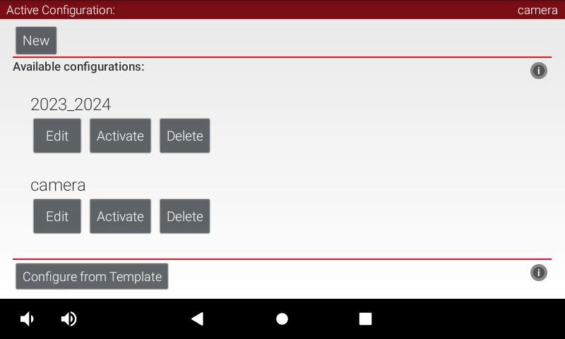
At the driver station's main screen, tap the three-dots button at the top right and select “Configure Robot”.
-
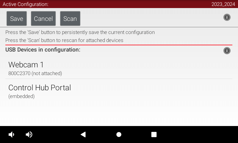
Tap the “Edit” button of your existing robot configuration.
-
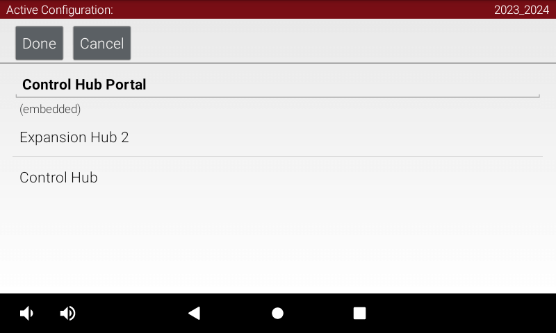
Tap the “Control Hub Portal” within your robot configuration to see its connected control and expansion hubs.
-
Tap “Control Hub” to view categories of connected peripherals.
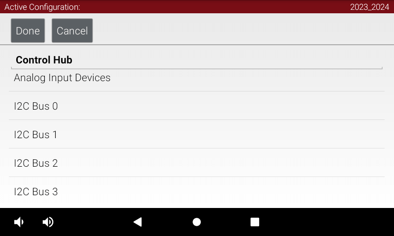
-
Tap “I2C Bus 0” to configure sensors connected to the first communications channel. The control hub's internal IMU is hardwired to this I2C bus.
-
Look for any entries of “REV Control Hub IMU” and disable them by selecting “Nothing”.
Note: Do not add your external IMU on this I2C bus, since the unified
IMUinterface code for reading measurements will ignore your configuration and try to talk to the original internal IMU instead. See the next section for adding your external IMU to a different I2C bus.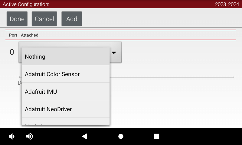
Add External IMU
Second, add the new external IMU to a control or expansion hub:
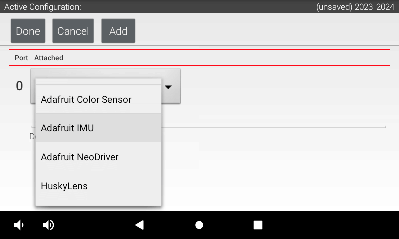
-
Now go to I2C Bus 1 and add an “Adafruit IMU”.
-
Name your external Adafruit IMU sensor to match how your code gets a reference to it (such as using
hardwareMap.getin Java). In the next section's code sample, we will use the name “imu”.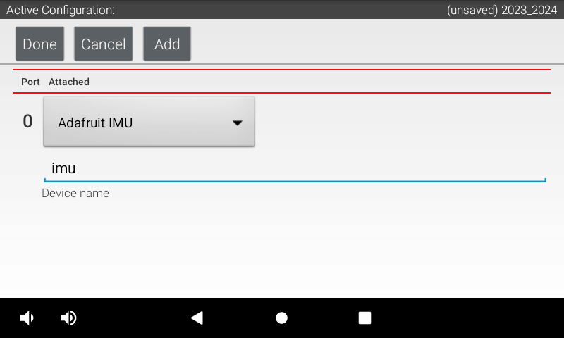
Sample Code
The code below shows how to setup your new IMU. Make the name of your imu matches the name in IC Bus 2 slot on your drive hub. Another thing to note is the Orientation we have given about our IMU. This changes depending on how you have your external IMU positioned.
package org.firstinspires.ftc.teamcode;

import com.qualcomm.hardware.rev.RevHubOrientationOnRobot;
import com.qualcomm.robotcore.eventloop.opmode.LinearOpMode;
import com.qualcomm.robotcore.eventloop.opmode.TeleOp;
import com.qualcomm.robotcore.hardware.IMU;

import org.firstinspires.ftc.robotcore.external.navigation.AngleUnit;
import org.firstinspires.ftc.robotcore.external.navigation.AxesOrder;
import org.firstinspires.ftc.robotcore.external.navigation.AxesReference;


@TeleOp(name = "External IMU Test", group = "Teleop")
public class ExternalIMU extends LinearOpMode {
    public IMU imu;

    public void runOpMode() throws InterruptedException {
        //Set up external IMU from I2C bus 1
        imu = hardwareMap.get(IMU.class, "imu");
        IMU.Parameters imuParameters;

        //Parameters for IMU
        imuParameters = new IMU.Parameters(
            new RevHubOrientationOnRobot(
                //The iMurdockUnit holds its external IMU in the same orientation
                //as an internal IMU, so you can copy your original values here.
                RevHubOrientationOnRobot.LogoFacingDirection.UP,
                RevHubOrientationOnRobot.UsbFacingDirection.BACKWARD
            )
        );

        imu.initialize(imuParameters);

        //Reset left-to-right rotation
        imu.resetYaw();

        waitForStart();
        while (opModeIsActive()) {
            telemetry.addData("🧭 IMU Rotation (degrees)", getAngle());
            telemetry.update();
        }
    }

    public double getAngle() {
        return imu.getRobotOrientation(AxesReference.EXTRINSIC, AxesOrder.ZYX,
            AngleUnit.DEGREES).firstAngle;
    }
}